5. LUCA Flows
LUCA Flows is the automation and orchestration module of LUCA BDS. It allows designing and executing workflows through a visual interface based on interconnected nodes, without the need to write code.
Each flow defines a sequence of steps—inputs, transformations, conditions, and outputs—that can be connected to each other to automate tasks of integration, data processing, or notifications.
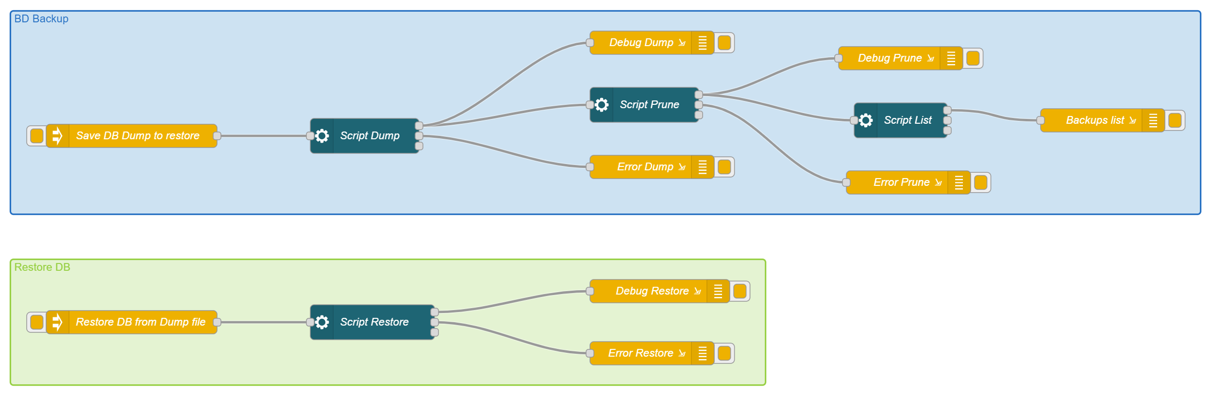 Figure 5.1: Flow Management
Flow Editor
When creating or editing a flow, you access the visual editor, which is divided into three main areas:
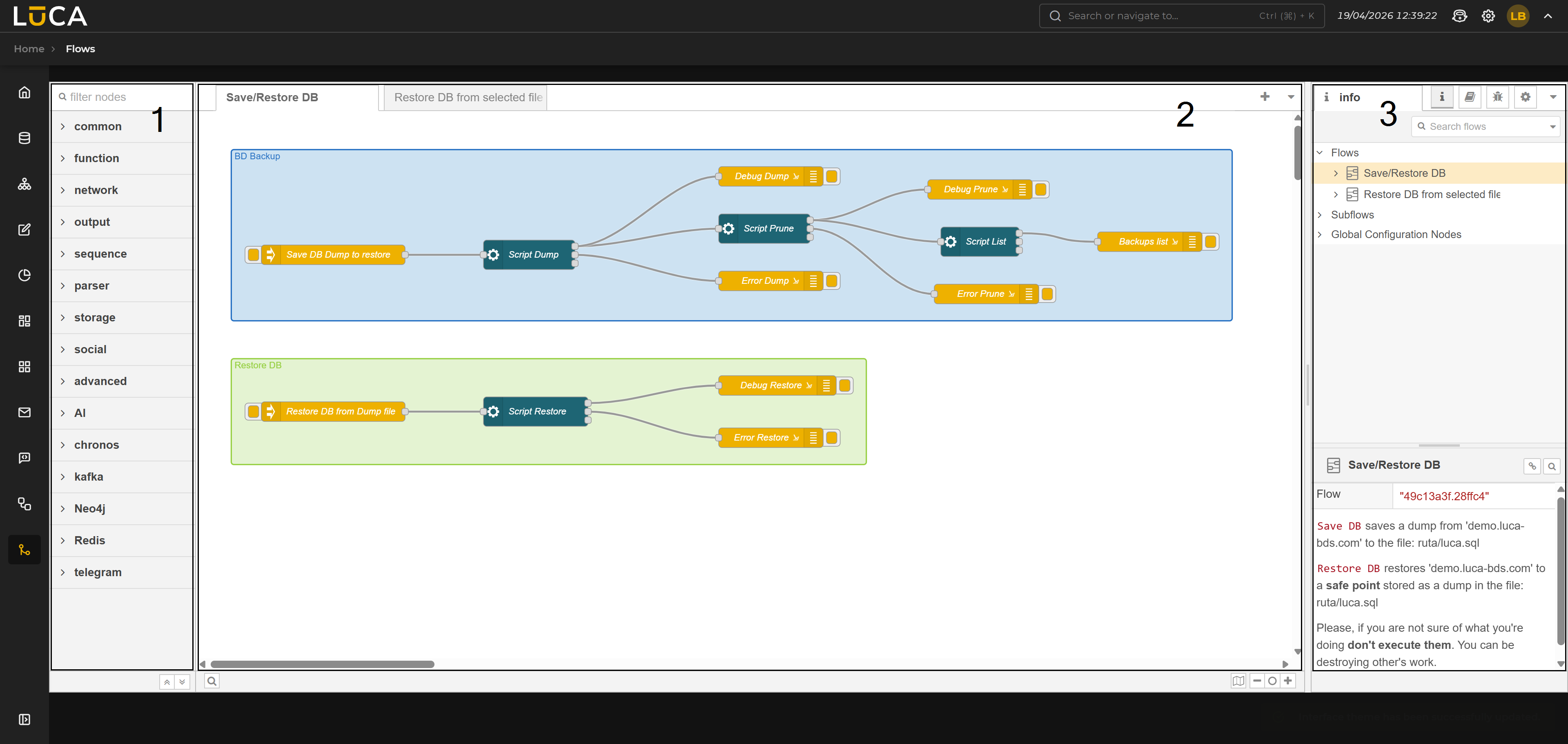 Figure 5.2: Flow Editor
Node Palette (1): Left sidebar panel with all available nodes, grouped by categories (for example, common and function). At the top, there is a text field to filter nodes by name. Workspace (2): Central space where the flow is constructed. Flows are organized into tabs; each tab corresponds to an independent flow. Nodes are dragged from the palette and connected to each other in this area. Right Sidebar Panel (3): Contains several utility tabs:
- Debugging: displays in real time the messages emitted by the debug nodes of the active flow. Allows filtering by node or viewing all.
- Information: displays the documentation of the selected node.
- Configuration: management of reusable configuration nodes.
- Settings: general options for the editor.
At the top right of the workspace, there are buttons to add new flow tabs and the additional options menu.
Nodes
Nodes are the building blocks of a flow. Each node performs a specific function and communicates with adjacent nodes via messages. They are classified into three types based on their position in the flow:
Input Nodes: Start the flow. They can be triggered by an event, an HTTP call, a timer, or a manual action. Processing Nodes: Transform, filter, route, or enrich the data of the message they receive before passing it to the next node. Output Nodes: Represent the final destination of the flow: writing to a database, sending email, calling an external API, or other actions.
To add a node to the flow, simply drag it from the palette to the workspace. To configure it, double-click on it and complete the options in the properties panel.
Connections
Nodes connect to each other by dragging from the output port of one node to the input port of the next. A node can have multiple inputs and outputs, allowing the construction of branched or parallel flows.
To delete a connection, select it by clicking on the cable and press the Delete key.
Deployment
Once the flow is designed, it needs to be deployed to become operational. The Deploy button in the action bar publishes the changes made. Until it is deployed, modifications do not take effect.
A flow in undeployed state keeps the previous configuration active. Changes in the workspace are only drafts until Deploy is pressed.